... that's me
So, here's a nice quick and useful project (for a change!). At work, hanging round the EE types, trying to pick up tips or pick up ideas or just pick brains, I see that they use these fume extractors so that they don't breathe in the nasty stuff that gets produced when the flux burns off as you're soldering...
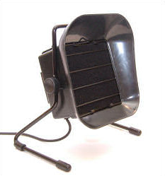
You can buy something cheap and cheerful if you like, but - I thought - much better to make your own, with a few tweaks.
So, rather than having the fan switched on all the time, how about automating it so that it would switch on and off when necessary, without me having to touch anything?
Sounds good.
Even better would be if I could place it just adjacent to the PCB I happened to be be working on, and then as I approach the board with my soldering iron, the fan could switch on and ramp up speed to suck (or blow) away the fumes until I moved my hands away again. Cool eh?
Well I thought so too.
4-pins on my fan
So, I had an old (well old'ish) PC case fan with the requisite wires necessary for controlling the speed. The four pins are used as described in this PDF, which I've summarised below.

The 12V and GND are self explanatory, and just supply the fan with power. The green sense pin is optionally used if you want to read back the actual speed of the fan, and I'm not concerned about that. The important one here is the blue "control" pin, which is actually a Pulse Width Modulated (PWM) input that you can drive to control the speed of the fan. Internally, the fan pulls this up to 5V (according to the spec) or 12V (according to my measurements, which I'm glad I double-checked!) and you can pulse it by pulling it low. So, by default, if it's unconnected, it's effectively full on.
PWM, as you can read in this SparkFun tutorial is a simple waveform that has a variable proportion of on-time to off-time at some fixed frequency. In the case of the 4-pin PWM fan, the standard specifies 25kHz (give or take a bit) as the frequency.
So, a picture being worth a thousand words, courtesy of SparkFun's CC license, this is what it means:

As you can see, the duty cycle can be used to convey information to the device you're controlling. The length (i.e. time) of each period is defined by the frequency, so for 25kHz, that's a period of 1/25000 or 40 microseconds. So a duty cycle of 75% means that the line is high for 30 microseconds then low for 10 microseconds; 50% means it's high for 20 microseconds then low for 20 microseconds; 25% means it's high for 10 microseconds then low for 30, and so on.
4-pin fans normally respond to a subset of the full 100% range of duty cycles and will commonly spin at some predefined minimum RPM below say 20%. This is to ensure that there is always some airflow in case of problems. The datasheet for the particular fan you choose should show the details. For example, for the fan I'm using, the chart looks like so:

You can see that with 12V, you can't make the fan spin at anything less than about 400RPM.
Ok, how to produce this variable PWM signal? Well, a PIC of course!
To bit-bang or not ...
It would be possible, and pretty simple, to use a timer, an interrupt routine and a bit of code to pull a pin low according to whatever duty cycle you choose. But, with some PIC devices, it's even easier than that because the PWM behaviour is encapsulated in a dedicated hardware module on the chip and you can configure it with a few register settings and then you're free to do whatever else you like (or need) in the code.
For example the tiny 8-pin PIC12F1822 has more than enough to do what we need. The particular feature to look for is the "ECCP (Enhanced/Capture Compare PWM) Module" - it may come in slightly different terms on other devices but PWM is often associated with CCP (capture and compare) peripherals as it's easy to provide both functions from similar hardware.
The PIC12F1822 also has a 4-channel 10-bit ADC, which we'll need for the proximity sensor. More of that later. For now, we need to figure out what to put in the registers that control the PWM output.
The PIC uses one of its 8-bit timers, TMR2, in the PWM mode, so the registers that control the frequency (i.e. period) and duty cycle are PR2, T2CON, CCPR1L and CCP1CON. The datasheet also gives the crucial equations that we can use to determine how to set the right values.

The annoying thing is that the equations aren't written in the way we need to use them. For example, equation 24-1; we want to know what value to set to PR2. We already know the period we want (40 microseconds) and our clock frequency, Fosc, (in this case I've configured the PIC to use its internal 8MHz oscillator), so we just plug in what we know to the equation and rearrange it to get PR2.
So, PR2 = (Period/4*Tosc)-1, which with our period of 40 microseconds and Tosc of 1/8MHz, gives us PR2 = 79. Simple eh? It would be much simpler if the datasheet just gave that formula in the first place because I expect most people would start with what they know to calculate what they want [sigh].
Anyway, now we know PR2, we only need to calculate how to set the 10-bits that are spread over all eight bits of CCPR1L and two bits of CCP1CON. Confused? Yes - why not just have a bigger register? Well, because it's an 8-bit PIC I guess, so it makes sense.
In any case, we only need to mess with equation 24-3 now because we want to specify the duty cycle ratio (that's our 25%, 50%, whatever) to get the corresponding value for CCPR1L:CCP1CON<5:4>.
Looking at equation 24-3, it's obvious that if we set it to zero, it will give zero percent duty cycle. What about 100%? Well, like we did with equation 24-1, we just rearrange it and plug in what we know. As we already calculated PR2 to be 79, we know that the denominator, 4(PR2 + 1) must be equal to 4*(79+1) = 320. Then with our desired duty cycle of 100% (i.e. a ratio of 1), we can see that setting CCPR1L:CCP1CON<5:4> to 320 will give us 100%.
Perfect.
We can scale other percentages accordingly, so a percentage between zero and 100 will be scaled to a value between zero and 320, and write a simple function that takes a percentage and sets the correct values in the registers:

So, you can see from the above equations where the magic number of 320 comes from in that code, and the two lines in the middle are just splitting the 10-bit value into two registers.
The final line is used to turn off the fan completely if the duty cycle is zero - remember that the fan has a minimum speed, even if we set the duty cycle to zero, so I've configured another PIC pin to switch a MOSFET that cuts the power to the fan when I really want it off. You'll see that in the schematic.
Speaking of schematics ...
It's probably time to show you what I've done.
Perhaps not a lot of explanation needed, but just in case....
The main power is 12V, so there's a jumper (JP1) drawn there so I can connect to my PSU. The PIC only needs 5V, as does the proximity sensor, so I have 5V voltage regulator with associated smoothing capacitor providing the power to the logic.
Pin 5 (RA2) is the one configured for PWM output, which pulls the fan's control pin to ground via a 2N7000 MOSFET. The crucial thing to note here is that all of the talk about PWM above, with the various percentage duty cycles, assumed that this relates to the percentage of time the output is high. Whereas, the fan's control signal is pulled up internally, so it's by default high, and we want to pull it down to slow the speed. Luckily, this is trivial to do with the PIC because we can simply flip a bit to choose whether the PWM output is active-high or active-low. Look at the specification of CCP1M in the CCP1CON register in the datasheet. Very nice.
As I mentioned in the code snippet about, pin 6 (RA1) is used as a low-side switch to allow me to switch the GND connection to the fan on or off. Effectively switching the fan off whenever RA1 is not high.
The final part of the puzzle is the proximity sensor, which is fed in to one of the PIC's ADC channels, so I can read the approximate distance from my hand/soldering iron during operation. This connects through JP2, and has a 10uF capacitor to smooth out any bumps as it draws quite a bit of current. I'd better tell you about that next.
Getting closer ...
So, the proximity sensor I chose is the Sharp GP2Y0A41SK0F, which outputs an analog voltage of between 0.3V and 3.1V over a range of 30cm to 4cm respectively.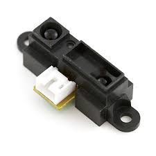
In testing, I recorded outputs of zero to 3.2V on my oscilloscope, so that's the way I've coded it.
Code .... just a little bit ...
Which is true. There's hardly any code in this project, and I'm only using a tiny fraction of what the PIC can do. It seems a waste, but there you go .... you can buy a lot of features for very little cost these days.So, the code.
Leaving aside the configuration bits and other housekeeping gubbins (you can download the whole source code below as usual), the main function starts out configuring the internal oscillator and setting all pins as digital except the ADC channel we're using (that's AN3 on RA4).

Next, we configure the PWM module. This is where we load PR2 with our calculated value of 79, and set the correct bits in CCP1M to use PWM in active-low mode. The remainder of the code just configures TMR2 with a 1:1 pre-scaler and then kicks everything off.


Note that the code forces anything less than 15% to zero, so we switch off the fan at the point where it will no longer respond to lower duty cycles (remember that chart from the fan's spec?). Also, even though we have a 10-bit ADC available, I disregard the lower two bits because it simplifies the code and we don't need that precision anyway.
Laying out the board
Now, this is a nice small and tidy circuit, so I decided to stop using the mysterious and slightly intimidating auto-routing features that Eagle provides and made this the first board that I routed manually.I've used thicker traces, and actually it looks pretty good to me and the auto-router didn't do anything other than complicate matters. So I think I'll be routing manually from now on.
Here's the layout:

And here's some pictures of the assembled board.


Seeing is believing ...
As always, we have to prove that the damn thing does what it's meant to do, even though I haven't yet put it in a nice enclosure (and probably won't because I've had my fun now!).So, I've hooked up the power supply, the fan and the proximity sensor like so...

... and I've recorded a short video of the gizmo in action ..... enjoy!
No comments:
Post a Comment