Monday 16 June 2014

Seeing double ...... triple?

As I mentioned in another blog post, the ImageMerge software that I've been developing proved to be enormous fun during testing.

Not having an endless supply of images to merge, I came up with a simple plan to test the merging part of the software (rather than the registration). So I set up the camera on a tripod, placed in the lounge in a suitable position, and - using the self-timer - took pictures from identical viewpoints but with different content.

The "different content" in this case being me.

The very first attempt used three source images, so I merged two of them first and then merged the third with the result of the first step. One of the images was slightly out of focus, so I wasn't too happy with the result, but it did lead on to some more experiments.

Anyway, for the sake of posterity, the first "triplet" image, started with these three images:


The resulting merged image came out like so:


Could do better ...

Now, given that I'd not only posed myself in different positions, but also tried out different facial expressions (if you can call them that!) to try to show three different characters, it started me thinking....

Getting carried away, I then came up with this ....


... and this ...


... which, after two more merges, turned into this .....


Like father like son ....

Seeing some of the hilarity these produced when posted on Facebook, my dearest son couldn't wait to get involved and so we tried one (two?) of him indoors ....


... and one (three?) of him in the garden .....


.... which is enough frivolity for now, so back to some real work soon ......

Wednesday 4 June 2014

Windows on history

Did you ever see ...

This excellent blog post that displays how Russian photographer Sergey Larenkov uses Photoshop to merge old and new photos to produce some really compelling images that help to bring history alive?

Well, it got me wondering how tricky it must be to get exactly the right point from which to take the modern version of the photo, not knowing exactly where the original photographer was standing, what lens he used, what focal length, zoom etc. So it's actually quite difficult to get two suitable images for merging..... even if you can afford Photoshop (I can't) ....

So, given that writing software in general, and image processing in particular are what I do in my day job, I knocked up a - hopefully - simple-to-use application that not only corrects for slight differences in perspective, but also rescales images as necessary and provides an easy way to do the merging. As an example, taking a historical picture from the online archives of my home village ...


... together with the present day equivalent, taken by yours truly on a cold Sunday morning ....


... I was easily able to produce this merged composite ....


... which is not a bad result, if I say so myself.


Go on then, give us the software ....

Ok, if you have Windows 7 or Windows 8, or 8.1, you can download the installer from here and give it a bash. No guarantees, no warranty, etc. this is all an alpha release and subject to bugs, problems, incompatibilities, whatever, but if you want it, here's how you do it, using the above images as an example ...


Image merging the easy way ...

First off, you need at least two images. I say "at least" because you can merge multiple times and have an infinite number of them, but you can't have less than two. You just can't.

The images should be of the same scene, and should be taken from roughly the same position but do not need to be the same size or format, the program will take care of resizing and mapping one image onto the other to make it easier to merge them together. 

So, when you start the application, it looks something like this ...


The user interface is similar to Microsoft Office, with a ribbon at the top and some shortcut options for loading, saving etc. at the top left. Everything is controlled by the ribbon options, moving from left to right. Different options will be enabled/disabled as you proceed, so you really can't do anything inappropriate. Well, not with this software anyway ...

So basically, you follow these steps:
  • Load two images – using the “Select images” panel on the ribbon
  • Mark corresponding points – using the “Mark and merge images” panel
  • Paint areas where you want the secondary image to show through – using the “Composite image” panel
  • Finally, adjust the blur and save the result – using the “Save results” panel
These steps are described in detail next ....

Select the images


The images are arbitrarily called “primary” and “secondary”. The primary image is the one that the bulk of the content is expected to come from and will form the basis of the final result. The secondary image is the one from which selected areas will be merged into the primary image.


So, click the Primary and Secondary buttons - in any order - to load two images ...

You can pan and zoom each image and can adjust the vertical splitter bar to adjust how much of each image you see. Use the mouse scroll-wheel to zoom in or out and just click and drag with the left mouse button to pan the images. Each image can be panned/zoomed independently.

The next step is to mark a number of reference points on each image so that they can be correctly registered. Moving on …

Mark and merge

On either of the images, find a suitable reference point, such as a corner of a door or window frame, that you will be able to locate fairly accurately on the other image. Zoom in to get more accuracy and then right-click once with the mouse to mark a green spot at that location.

As you do so, a corresponding marker will be added to the other image in an approximately similar position. It’s not always easy to see, so you may need to zoom in or out to find it. 

When you’ve found the marker that was added to the other image, left-click and drag on the marker itself to move it to the exact position that corresponds to the reference point you chose in the first image. Get it?

Repeat this process until you have a reasonable number of marker pairs that are arranged over significant parts of the image. For example ...


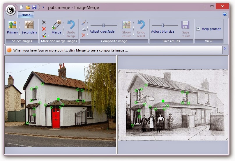
If you left-click on a marker in one image, it turns to solid green and the corresponding marker in the other image also turns solid so you can see which ones match. 

If you have clicked a marker, you can use the Remove option from the ribbon to delete that marker pair from both images, or you can click Clear to remove all markers if you want to start again, and if the green colour is not visible enough, you can select a different colour using the Colour option.

Note that it's important that the marker points should identify medium-to-large, flat, two-dimensional areas, such as walls, doors, windows, signposts, etc. and should not all be in a single line. If they are, or if you don't have enough points, the next step might look a bit weird. No, it will look a bit weird ....

So, when you have marked at least 4 points (but ideally 7 to 10 - the more the merrier), click the Merge button on the ribbon to move to the next step...

The composite image ...

If everything went ok, you should see a composite image with a nice pink glow. This will be the primary image but with the secondary image – correctly positioned and sized – showing as a cross-faded ghost. 

If this is not happening, in other words, it does look weird, then as I said above, you probably didn’t choose enough good marker pairs in the previous step. In which case, click Undo Merge to return to the previous step and either adjust your marker positions or add some additional ones to get a better registration.

Using the images above, the following screenshot shows the sort of thing to expect. You can see that the primary image is unchanged (apart from looking pink!) but that the secondary image has been distorted – technically, it’s undergone a perspective warp – and scaled (stretched or shrunk) so that the reference points you marked are as near as possible coincident with those in the primary image. Use the Adjust crossfade slider to fade between the two images to check the registration ...

Now what you do, is to right-click and drag with the mouse to “paint” the areas of the composite image where you want the secondary image to show through. 

These areas will be shown in green as in the example below ...


To paint finer detail, just zoom in before painting – the size of the paintbrush doesn’t change, so the thickness of the brush depends on your zoom level. This is much easier (in my humble opinion) than having to select a particular brush size.

If you mistakenly paint some green areas where you didn’t want to, click the Erase button on the ribbon and then right-click and paint again to return to the pink colour. Click Paint to get back to normal.

After you’ve finished painting the areas you want merged, click Show Result ….

Nearly done ...

At this stage, the primary image will be merged with the warped secondary image in those places you have painted. It should look ok, but maybe not perfect.

By default, the areas will be blurred so that there is a smoother transition, which makes it easier on the eye if the images are not similar colours (as in the above example). This means you might want to paint bigger areas and let the blur fade nicely...


... alternatively, use the slider on the ribbon to adjust the blur radius until you get the visual effect you want. If you mess up, just click Undo Result to return to the previous step and adjust your painted areas.

When you are finally happy, click Save Result to save the final image. Note that you must click the large Save Result button on the ribbon – this is different to the small save at the top left, which saves details of the image filenames, marker positions and painted areas, so you can quickly load a marked and painted pair for editing later.

Ok, enough typing – get playing and see what happens. You have already seen one of my ideas – current and historic photos - but you can also experiment with identical scenes but with different people (I'll post some of my triplets later!), or maybe the same scene at different times of the day, or different times of the year, etc.

See what you think ..... it kept me amused ....

Tuesday 3 June 2014

Hacking an optical mouse

Have you ever wondered ...

... how a mouse works?

I don't mean the real old fashioned kind, with proper balls and stuff, but an optical mouse or even a laser mouse (similar to optical but higher precision).

Well, I did. ... Wondered, that is ....

So, after Googling around for a bit and finding a number of hacks (like this one or this one or several others), I decided to have a go myself. Which is why I engineered an early exit from work on a Friday afternoon that resulted in me scuttling into Maplin to pick up an Arduino Uno for the best part of twenty-five quid (yes, I know they're cheaper online, but I'm not such a patient hacker) .... and on Saturday morning, I hunted in various boxes to find a sacrificial mouse ... this one .... (as with all the images, click to see a larger version in a new window)

Sacrificial mouse
Sacrificial mouse
Removing the single screw under the QC label gets the top off the mouse to reveal the relatively simple circuit inside. If you click to the full size view, you can see I've marked the LED assembly, the optical sensor - in this case a Unity MCS-12085 (just Google the numbers on the chip!) - a microcontroller (MX84510, but that's irrelevant 'cos we don't need it), the micro-switches for the mouse buttons and four wires heading off to the PS/2 plug at the computer end. I removed the scroll wheel temporarily to avoid dropping it repeatedly, which was annoying me after the seventh or eighth time ....
Top view before
Top view (before hacking)
After finding the datasheet for the MCS12085 optical sensor, to identify the pin-outs, it's easy enough to flip the circuit board over and find the four little beauties that are apparently the only ones we need to hack into the sensor itself. I didn't figure this out myself - I have to give credit to the earlier hackers, who already described the principle .... but anyway, let's press on ...

The four pins we need are two for power - GND and VDD (+5V) - the clock - marked SCK - and the serial input/output marked SDIO. Take a look at these on the image below and also note the connections to the existing PS/2 cable that I've highlighted in a yellow rectangle ...

Bottom view 1
Bottom view showing 4 pin-outs and PS/2 cable
Now if, like me, you're a lazy sort of bugger that can't be bother to hacksaw the PCB or drill holes into the copper tracks, like some of the other guys did, then you might sit and scratch your head for a bit and idly eyeball (visually trace) the existing connections to see where the four pins end up. This proves useful ...

The power and ground (VDD and GND) predictably end up at the outermost two wires of the PS/2 cable (because that's how the mouse is powered, after all), and the clock and data pins (SCK and SDIO) head off to the microcontroller - which normally drives the sensor and then outputs the processed PS/2 signals back to the 'pooter.

This is actually good news, because we don't need the microcontroller at all, and can remove it from the circuit and hook things up however we like.

So - in the image below - notice that two output pins from the right of the microcontroller connect to the remaining two wires in the PS/2 cable - the two between the marked VDD and GND inputs .... you see where I'm going with this?

Bottom view 2
Cunning plan forming ...
Well, what I'm thinking is that, with the controller chip gone, we just need to link the PCB tracks as shown below in red to get our four needed connections handily wired up to the existing PS/2 cable, with minimal need to physically fart around too much. Cool eh?

Bottom view 3
Cunning plan confirmed
So that's what I did.

I fired up the soldering iron, removed the microcontroller chip, and soldered links in to the PCB at the locations marked in red above. After doing this, the top view of the hacked mouse now looks like this ...

Top view after
Top view (after hacking)
Now just screw the cover back on the mouse and, to all intents and purposes, it doesn't look any different to when I started.

Except of course for the necessity to cut off the PS/2 plug and hook up the four wires to my Arduino. Something like this ...

Arduino
Arduino hooked up to the mouse sensor

The VDD and GND from the mouse go to +5V and GND on the Arduino, and I've arbitrarily chosen to wire the serial IO to digital pin 7 and the clock to digital pin 4.

Now breathe a big sigh of relief, because from now on it's all software, with which I'm much more familiar ...

... and after a bit of tinkering, I produced this Arduino sketch (click to download the source code) that provides a simple interface to the mouse sensor by typing commands in the Arduino Serial Port Monitor. Take a look at the code and you'll see what I mean - you can force the LED to be permanently awake (necessary to get a good image), switch it back to normal mode (where it will sleep after 1.5 seconds of no movement), and dump the 18 x 18 grid of pixel values to check that we get some kind of realistic data. Note that the pixel values are all in the range 0 to 63 because two bits of each 8-bit pixel are used to indicate data validity and start of frame - refer to the datasheet for the gory details.

Now, almost (but not quite) the final picture - here is the mouse attached to the Arduino, and all that's needed is to plug the Arduino into the USB port of the computer and try to get some output ....

Breadboard
Just add USB cable ...

... and here's a dump (if you see what I mean) from the Arduino Serial Monitor, in which you can "see" the pixel data returned by the mouse sensor ...

Pixel dump
Pixel values dumped as text

Now, looking at grids of numbers is not really why we started this, so I adapted the original Arduino sketch to provide a simple - but much faster - streaming output, which I then hooked into a C++ application to display the (rescaled) pixels as a grayscale image. You can download the streaming version of the sketch here, but I'm going to hold off on releasing the source code for the viewer for a bit because I have some more cunning plans for it in a later blog post ..... this could get interesting ....

For now, here's a snapshot of a single frame as seen by my sacrificial mouse as it glides effortlessly over an (unpaid) credit card statement ......

Pixel display

I'll post again soon with more .......... hope this was useful ....